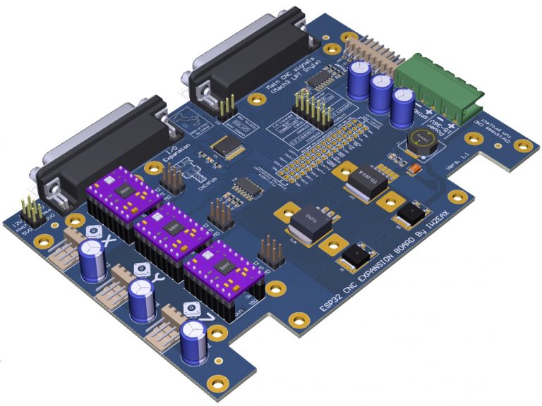
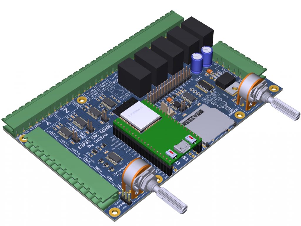
The boards are updated to 1.1 version!
Here’s a recap of the situation:
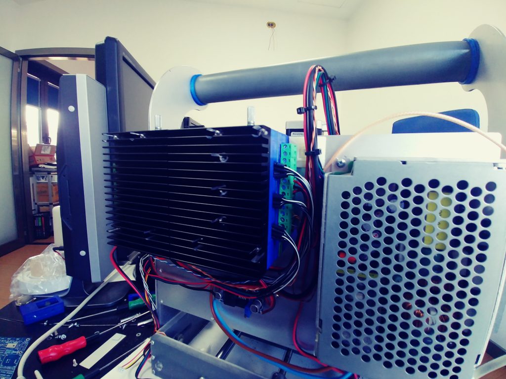
After the first tests, everything seems to be working fine.
As shown in the videos that I posted in the past few weeks, the controller has been functioning properly both in “MILL” and in “LASER” mode.
These tests have given me the chance to check the hardware and think about some improvements I could make to the boards that will be produced.
Here are the results:
Errors I fixed
- I corrected the position of 4 out of the 8 mounting holes both on the motherboard and on the expansion board (1mm offset on the X axis).
- I corrected the silk screen names “CHARGE PUMP” and “DIGITAL ENA” of the JP3 jumper (expansion board) because they had been swapped by mistake.
- I changed the power supply of IC2 (74HC14) to 5 Volts. It was connected at 3.3 Volts by mistake, but should be powered at 5V (otherwise the signals on the LPT would be mixed, some at 3.3V and some at 5V).
Improvements and modifications
- I added dual footprint for the ESP32 module (900mils and 1000mils) to increase the possibility of using different boards available on the market.
- In order to improve safety, I eliminated the DOOR button and inserted a PANIC! button in its place.
- I added the DRIVER-ENABLE pin coming from the CPU-ESP32 in order to be able to switch the steppers on and off via software.
- I added a PANIC button to disable the stepper motors, the spindle PWM and the spindle ENABLE. For safety reasons, the PANIC button has a higher priority over the software control coming from the ESP-32 DRIVER-ENABLE pin.
- I added the direct drive of a small spindle (100/150W) working in PWM.
- I added a step-down DC/DC converter in order to unify the power souces (CPU-STEPPER-SPINDLE) if needed. By using a few jumpers, all the power supplies can also be unified in order to use a single power supply unit.
- The full kit (motherboard + expansion board) can now work with three different power supplies:
- 12Vcc for the motherboard
- 12-40V max for the stepper motors
- 12-48V max for the spindle working in PWM
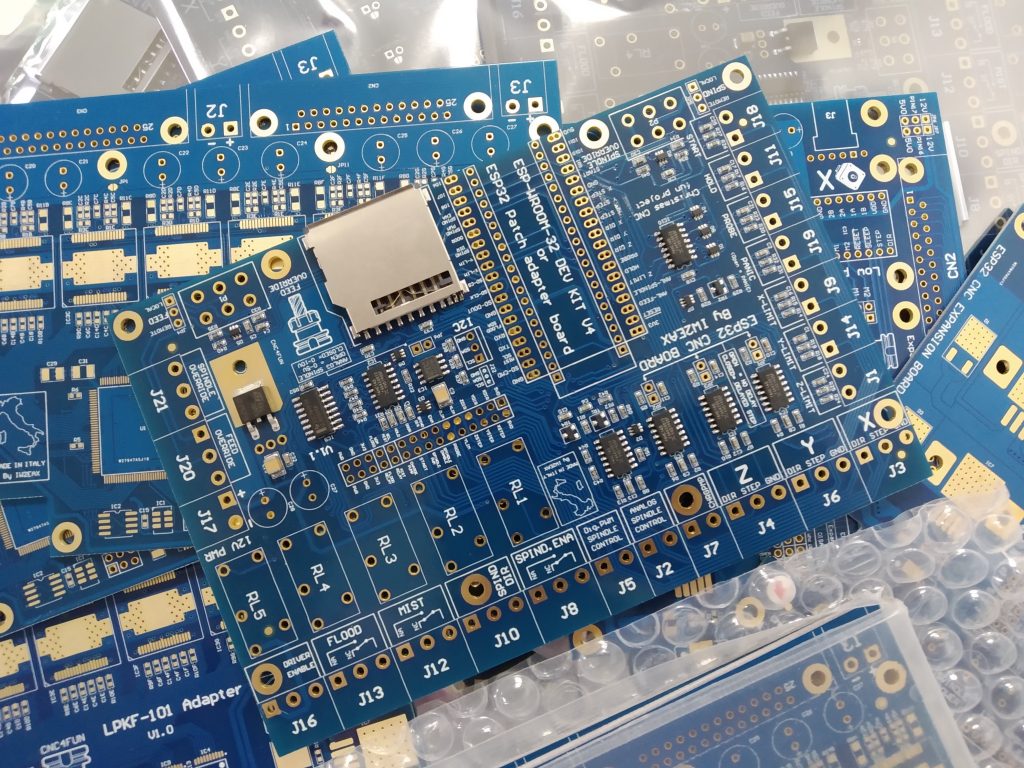
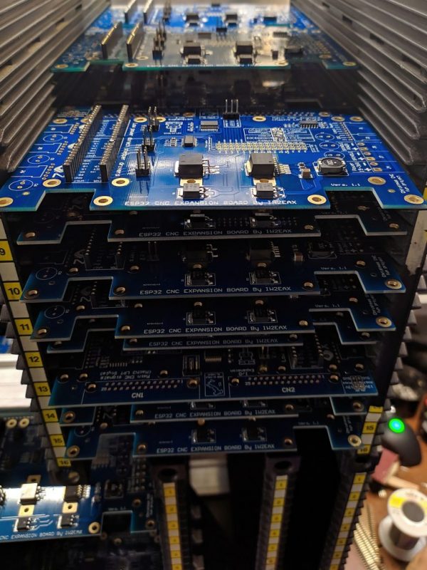
The next step will be testing the latest PCB version (1.1). If no other errors are detected, I will then start thinking about producing a first lot of boards.
Stay tuned!